
.png)

Vibration Control of Mode Shapes Coinciding with Blade-Pass Frequency (BPF)
This project required manipulating local mode shapes and natural frequencies so they did not coincide with blade-pass frequency bands.
Was that necessary—or was there an easier solution?
Vibration Test Profile
The rotary-aircraft vibration profile (MIL-STD-810) combines broadband random vibration with discrete rotor blade-pass orders.
In the breakpoint diagram, a random spectrum is overlaid with four discrete BPF orders (A1–A4) representing sinusoidal components from the rotor system.
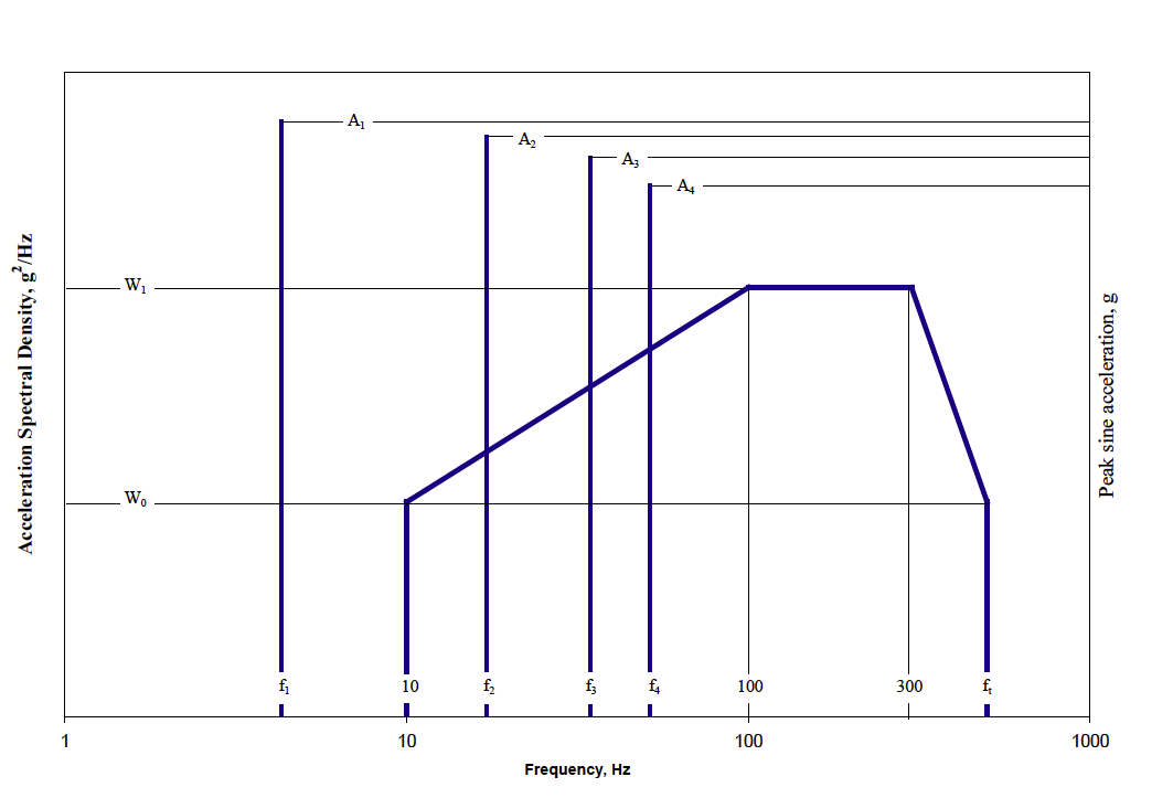
The Vibration Profile in Detail
For a turbine-powered helicopter, 10–400 Hz is dominated by random vibration representative of engine operation.
The four An lines are sinusoidal BPF components present on the airframe. Their exact frequencies vary with rotor speed.
Because rotor speed changes, the BPF orders have bandwidths. Any structural natural frequency falling within those bands risks forced-response amplification.
Case Study
Here, the goal was to design the instrumentation and its support structure so no natural frequencies coincided with the BPF bandwidths.
Weight matters in aerospace: lighter is better—less fuel, lower cost. The power distribution unit (PDU) enclosure used 1.6mm aluminium sheet: very light, but with low vertical stiffness.
The Problem
During shaker testing to the rotary MIL-STD-810 profile, the main contactor inside the PDU opened at the A1 BPF. The contactor was mounted vertically, aligning its sensitive axis with the dominant excitation, while the enclosure floor lacked vertical stiffness.
Controlling the Vibration
With an ultra-light enclosure, stiffness was the key lever. By changing the geometry/topography (beads, flanges, fastener pattern), we shifted local modes so natural frequencies no longer coincided with BPF bands.
Was There an Easier Way?
Yes. Before structural changes, we rotated the contactor so its sensitive axis aligned with a lateral/longitudinal direction—axes that had higher stiffness and much less amplification than the vertical axis. This quick change eliminated the opening at A1 BPF. Lightweight stiffening was then applied for robust compliance across all BPF orders.
Further Information
For help with vibration control in rotorcraft or other harsh environments, call 01908 643433.
We’re here to help.